User Guide - Version 2.1
First Published: 24-01-26, Revised: 24-05-10 (v2.1.0) See Appendix A
Copyright: ©2024 Thomas R Schmidt, Wildwood IL USA
Foreword
This User Guide provides you with a step by step approach to a successful integration of your Hikvision cameras into your HE system. This is not a “plug n play” driver but will be once you’ve gone through the process outlined in this document, so please take the time to do so with your first camera. There are critical configuration requirements for your cameras and NVR before you can use this driver. So let’s get started with the unique features this driver offers.
These features are designed to fully integrate your Hikvision IP Cameras into your HE system for comprehensive home and small business monitoring and alerting purposes.
- Your Choice of Driver: Alarm Server, Controller or Both
- Trigger Alarm Input Events using HE Sensors, Rules and HSM Intrusion Alerts
This feature gives you unlimited flexibility to receive Hikvision notifications and start recording when events in HE occur. - Proxy Motion Sensor in HE
Provides advanced event message handling to consolidate mulitple motion alerts from the camera into one motion event on HE, with button pushes limited to one button push per feature per event. Motion is cleared using a reset interval in minutes of inactivity that you configure in preferences. - Alarm Server Logging and Event Reporting
Comprehensive logging provides all you need to know about the activity being reported by your cameras. - Support for 8 Motion Detection Features Available on Hikvision Cameras
Includes Basic Motion, PIR Sensors, Intrusion, Line Crossing, Region Enter/Exit, Object Removal and Unattended Baggage. These features were selected as those most applicable for home and small business monitoring purposes. Video Tampering is also supported. - Enable/Disable (Arm/Disarm) Motion Detection Features
All at once with a single command, or with selective filtering. - Coordinate Arming/Disarming your Cameras with changes in Mode and/or HSM
A few simple rules in RM is all it takes. - Enable/Disable Alarm Input Handling
Allowing you to control when Alarm triggers from HE will be accepted. - Control and Monitor Cameras connected to a Hikvision NVR Subnet
Specific requirements apply and not all NVRs may be supported. - Easy to use Commands and Integration with RM
Your camera will appear as a Switch, Actuator, Motion Sensor and Button
Use the Actuator commands Enable/Disable to Arm/Disarm Motion Detection features.
Use the On/Off commands to Trigger and Clear the Alarm Input Event.
Monitor motion on the device in HE for motion on your cameras
Monitor pushed to determine which Motion Events are triggering events in HE.
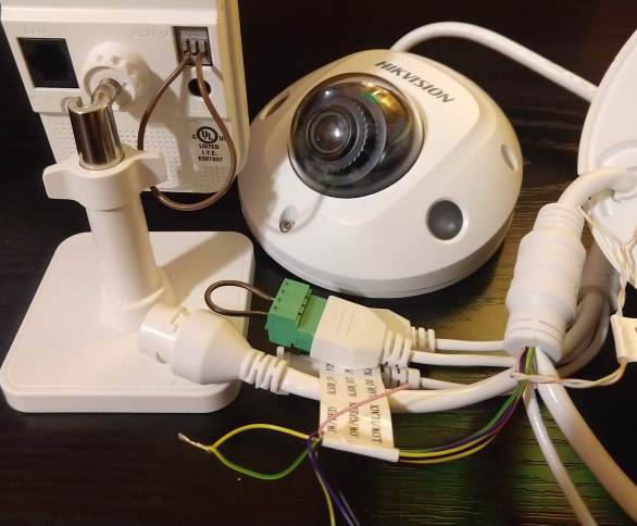
To use the feature that allows you to trigger Alarm Input Events, your camera must have wired Alarm I/O ports that are accessible and not in use. Because for this to work, you will need to connect the In/Out ports with a jumper wire, or simply connect the two wires labeled Alarm In/Out. This will not damage your camera. It is required since the driver is only allowed to trigger Alarm Out when using the Hikvision API (i.e. ISAPI). The API does not not allow apps to trigger Alarm In.
When Alarm Out is triggered, the camera switches a dry contact relay on the ouput port from open to closed, nothing else. This exposes a closed circuit over the jumper wire to the Alarm In port and its relay, which is all it is waiting for in its NO state. When it senses a closed circuit, the Alarm In relay closes and the event fires.
When the Alarm is cleared, the output relay opens and so does the circuit to Alarm In. There is no voltage applied. Voltage is only present when there is a powered sensor (input), powered siren (output) or powered security system control panel connected. The reason you don't need to connect the grounding ports is because both relays share the same path to ground in the camera.
You can and should first read the Disclaimers below and then test this yourself by connecting the ports, enabling and arming your Alarm Input and Output Events, and then triggering a manual alarm from the Alarm Out event on your camera (don't forget to clear it). See additional notes on the jumper wire in Camera Configuration below.
If you can't use the Trigger feature, you can still use the driver to control the arming schedules for motion detection features and use the Alarm Server if your camera supports that feature.
For the Alarm Server
Important: Do not configure the Alarm Server on the camera until you have created the device in HE and successfully Saved Preferences. If your Alarm Server is currently configured for some other device on your hub, reset the Alarm Server configuration to defaults and remove that device from HE before proceeding. This is the only requirement.
After saving preferences, configure the Alarm Server as follows:
Network> Advanced> Alarm Server-HTTP Listening
| Destination IP: <hub ip> | URL: / | Protocol: HTTP | Port: 39501 | ANR: unchecked |
Then, go through all Basic and Smart Event Linkage Methods, including Exceptions, and select Notify Surveillance Center for all events you want the Alarm Server to receive alert messages for.
For the Controller
| Setting | Requirements |
|---|---|
| System> Security> | Web Authentication = digest/basic |
| Network> Advanced> Integration Protocol> | Hikvision-CGI Enabled, Authentication=digest/basic Note: Newer cameras may not require this setting. Do not confuse this with the OVPN service. |
| System> User Management> | Create an Operator user account for Hubitat with the Remote Parameters/Settings and Remote Notify options selected. The driver does not support use of the Hikvision admin account. The Operator account will be validated when saving preferences. |
| Motion Events | Disable and set Arming Schedule to 24/7 for all driver supported Motion Detection features you want to control with HE. You will enable them later when Validating Operations |
| For Alarm I/O | All Events > Linkage Methods > Trigger Alarm Out NOT selected. |
| For Alarm I/O | Alarm Input> Arming Schedule: 24x7, Alarm Type: NO, Set desired Linkage Methods. |
| For Alarm I/O | Alarm Output> Arming Schedule: 24x7. Delay does not apply. Triggers from HE are immediate. |
Storage> Schedule Settings
If you will be triggering alarms and recording on the camera, click the Advanced button and set Pre-Record time to accomodate for the factors unique to your environment, that only real world experience can provide.
Refer to the photo above. Connect the Alarm In/Out ports with a small jumper wire, or simply strip and twist the Alarm I/O wires together if your camera does not have physical ports. Loose wires should be labeled. If not, the Hikvision standard is yellow/red for Alarm In and yellow/green for Alarm Out. For jumping ports, use bell wire. The ports will be marked I, O, In, Out, G, or Gnd. You may need a magnifying glass. Connect only the ports marked I/O or In/Out.
If using the Alarm Server, you must have NVR POE Subnet routing in place. If not, you only need to enable the NVR Virtual Host feature.
NVR POE Subnet Routing
| Setting | Requirements |
|---|---|
| NVR> Virtual Host | Enabled |
| NVR> Camera IP Config | Manual Mode |
| Camera> TCP/IP | Set Default Gateway to ip address of NVR POE Subnet Gateway (e.g 192.168.254.1) |
| Router | Define Static Route to the NVR subnet on the Router that the NVR is using as its default gateway. |
See Appendix B for screenshots of the required configuration elements.
This section of the document assumes you have experience with installing Community developed drivers manually using "import from url" or by using Hubitat Package Manager.
HPM is recommended for this driver. There may be new features added (submit your requests) and bug fixes, too.
The driver has these tags in HPM: Cameras, Alarm Systems, Motion Control, Monitoring, Safety & Security.
Or, right-click and copy the link for import of raw code.
You are now ready to configure your camera for operation with the Hikvision Camera Controller.
- Add a new Virtual Device
- Type “hik” in the device type filter
- Select the Hikvision Camera Controller
- Assign a name for this device in HE
Configure preferences as follows:
| Setting | Requirements |
|---|---|
| Driver Components | Select the components you wish to use. |
| IP Address | Camera IP: Local or NVR POE Subnet address Or NVR IP if connecting through the NVR Virtual Host (for Controller use only). |
| HTTP Port | For Controller: Enter Camera Port (default 80) or NVR Virtual Host Port (65001+). |
| Credentials | For Controller: Enter the userid:password of the Operator account. |
| Motion Reset Interval | Start with 1 minute for testing (default). See notes below under Alarm Server. |
| Event Counter Reset | Select a frequency. |
| Exclude from Controller | List of features to exclude from driver control (see notes below) |
| Exclude from Alarm Server | List of features that will not trigger motion or push buttons by the Alarm Server. |
| Name for Logging | By default, the driver will use the device Label. You may over-ride that here. |
| Debug Logging | Do not enable. See Errors and Troubleshooting. |
Include/Exclude Filters
The filter you enter here and when running the Enable/Disable commands is a string of lower case feature ids upon which no validation is performed. Use spaces, commas or periods as separators to improve readability.
ai = Alarm Input Handling
ao = Alarm Ouput Triggering
in = Intrusion
lc = Line Crossing
m = Motion Detection
or = Object Removal
p = PIR Sensor
re = Region Enter
rx = Region Exit
ub = Unattended Baggage
vt = Video Tampering
For the Controller, it is important to filter features you have but do not use or do not want to control with the driver to prevent the driver from changing its state when enabling/disabling “all available”. If you leave this blank, the driver will update the Exclude filter with the features that your camera does not provide when you Save Preferences.
Note: It is recommended that you exclude Alarm Output Triggering if you are unable to use it for any reason. This is especially important if the ports are already in use by a security system or other device.
Click Save Preferences
Validation for Alarm Server Only
No validation is required other than generation of the Device Network Id (DNI), which uses the ip address of the camera and must be unique among devices on your Hub. If it is, the Alarm Server will be ready to receive alert messages from the camera immediately after Saving Preferences.
Validation for the Controller
When using the Controller, the driver will validate and initialize your camera as follows:
- Prevent use of the admin account
- Send a GET request to the camera using the Credentials you entered. If accepted, the driver will extract the camera name, model and firmware version from the response and save those values in Data fields, along with your encoded credentials.
- GET the attributes of the account you have provided to confirm that it is an Operator with the required permissions.
- If using the Alarm Server, generate the Device Network ID using the camera ip address. If using the Controller only, the system assigned DNI will not be changed.
- GET the current states of all driver supported features, excluding any you have filtered, and initialize the device.
When validation fails, zDriver will display FAILED (refresh the page). Open the log to view the error message that will identify the problem. If you can’t get past this step, please report that you have a Hikvision camera that can’t be validated.
If all is well, zDriver will display OK (refresh the page). Your camera has been validated and is ready for operation.
Check the log to see what it found and reported back on.
If using the Alarm Server, go back and configure it now.
You may now start running commands and create test rules to validate its operation.
Tip: Use a Live Log in a separate window to view and confirm the results of your tests.
Test the Enable/Disable commands with and without filters and confirm the state changes on the camera.
Note: When running these commands without a filter, all supported motion detection features available on your camera, along with Video Tampering, will be switched to the requested state unless the feature has been excluded from driver control.
Alarm I/O
Test Enable/Disable with filter “ai” to confirm you can change the state of Alarm Input Handling.
Run the On command and confirm you receive the notifications you have configured for the Alarm Input event.
- On the camera, Alarm Output state will change from OFF to ON.
- On the device, state variable AlarmOut will change to active.
- Refresh the page to confirm.
If using the Alarm Server:
- The switch attribute will turn on as soon as the first alarm event message is received from the camera.
- State variable AlarmIn will change to active.
- Refresh the page for a minute or two to see how this camera behaves by watching the EventMsgCount go up. Some cameras will overload the Alarm Server with event messages every second. Others may report every 30 seconds.
For the Controller, the driver schedules a job to run 5 seconds after the alarm has been triggered in order to confirm the trigger has taken effect on the camera. If the Alarm Input event on the camera is active, the switch will turn on and AlarmIn will change to active. Refresh the page to confirm.
Run the off command to clear the alarm and never forget to do so. After the driver sends its request to the camera, it will set AlarmOut to inactive and schedule a job to run 1 minute later to reset AlarmIn to inactive and turn the switch off. The one minute delay is needed to accomodate the event reporting behavior of different cameras. Refresh the page to confirm.
If you have a camera with an audible alarm, check that option under Linkage Methods to see how fast the trigger is.
Alarm Server
Enable your Motion Detection features and start testing. Choose a camera that is convenient for testing purposes. Consider setting sensitivities high and thresholds low to trigger events more easily.
Check Events to verify button pushes and motion state changes.
Report any strange behavior.
After you have verified operations, start creating simple rules in RM to further validate its operation in your environment and help you discover ways to use it. For example:
- When Driveway Motion or Front Deck Motion is Active: Switch ON: Cam FD
- When Driveway Motion and Front Deck Motion is Inactive, Switch OFF: Cam FD
- When Mode becomes Night, Run Enable on Cam1, Cam2, with string parameter “in,lc”
- When Mode becomes Day, Run Disable on Cam1, Cam2, with string paramter “in,lc”
- When HSM Alerts Intrusion: Switch ON: All Cameras
- When HSM Alerts Cancel: Switch OFF: All Cameras
- When HSM Status reports Armed Away: Run Enable on All Cameras
- When HSM Status reports disarmed: Run Disable on All Cameras
IMPORTANT: Do not forget to turn the Alarm OFF in your rules when conditions go back to normal. As the examples show, if you have a rule with (conditions=true) that turns it on, you need a second rule with (conditions=false) to turn it off. Not turning off the alarm may eventually cause the camera to send out notifications every minute that the alarm is still active. In addition, some cameras may overload the Alarm Server with event messages every second, while others will report every 30 seconds. Trigger alarms for several minutes and watch the Event Message Count to test the frequency of your cameras. This also applies to Motion events. Not all cameras will behave the same.
Where to Find Your Camera in RM Actions
To Triggger and Clear Alarms, your cameras are in the list of Switches.
To run Enable/Disable: Select Action Type Set Variable, Mode or File, Run Custom Action, then select Action Run Custom Action, then select Actuator devices, then select the Cameras you want to control, then the Command, with or without a string filter parameter. No parameter or a null/empty parameter will switch all available motion detection features.
Integration with HSM
Use RM rules to monitor HSM Alerts and Status as the examples above show. It is recommended that you do not use the “Lights and Switches Alerts” feature of HSM to trigger alarms on your cameras since it is not designed for that and more importantly, there is no option to clear the alarm using HSM when the intrusion alert is cleared. Thus, you would still need a rule in RM to clear the alarm and then you would have critical actions being defined in two different apps.
Motion Reset Interval
Configuing the appropriate motion reset interval is important if you will be using rules to monitor motion on the camera and take actions based on state changes. The goal is to eliminate unneccessary state changes when activity is still occuring or may be expected. Start with 1 minute for testing and then increase to a more suitable value for deployment. The inconsistent nature of Hikvision motion detection features in terms of when and how frequently they trigger, alert and reset also comes into play. Not all cameras behave the same.
Motion Button
When motion is first detected by one of the supported features, the driver will push the assigned button for that feature.
The button will also be pushed ONCE for any subsequent motion event on the camera if it is different than the preceding motion event during the period of activity for this motion event in HE.
You will see this activity in the log. The accumulated “buttons pushed” for the last motion event in HE are also saved in the state variable, LastButtonPush.
Button Assignments
1 = Intrusion
2 = Line Crossing
3 = Basic Motion
4 = PIR Sensor
5 = Object Removal
6 = Region Enter
7 = Region Exit
8 = Unattended Baggage
9 = Video Tampering
This allows you to use the button as a trigger in your Rules so you can take actions based on the specific motion detection feature that triggered the event on HE or occurred within the same period of activity with other events.
Testing Buttons
You can use the Push command on the driver page to test your rules. This will not trigger motion on the device.
Alarm Server Logs
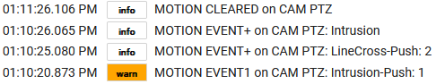
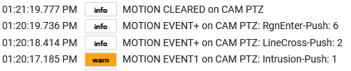
The first event is logged as EVENT1 and all others in that period of activity logged as EVENT+ if it is different from the previous event. Note how the button is only pushed once for each motion event that occurs within the period of activity.
Video Tampering Events
Video Tampering events will push button 9 but do not trigger motion. When video tampering is detected, the event will be logged and saved in state variables LastOtherEvent, LastOtherTime and LastButtonPush. LastOtherState will be set to active. Reset to inactive occurs 1 minute after the last video tampering event message is received from the camera.
Motion Duration Events
Events from motion detection features that provide a duration setting will be tagged in the log with “Duration”.
The Enabled/Disabled State variables for Motion Detection features and the Active/Inactive State of AlarmIn/Out change when a command is run that triggers it. Since you remain in control of these features on the camera, the driver always gets the current state of a feature from the camera first, to determine if a change in state is actually needed.
The switch attribute follows the state of Alarm Input on the camera, as described above in Validating Operations.
Alarm Server
The motion attribute is triggered active when one of the driver supported motion detection features that you have not excluded detects motion and sends an alert message. Reset to inactive occurs N minutes after the last motion event alert message is received from the camera, as defined in preferences.
The pushed attribute is set as described above and retains its value from the last push.
Driver
zDriver should remain OK at all times. When running any Controller command, if the GET request for current state times out or the ip is unreachable, zDriver wil be set to OFF and remain OFF until a command is run that sees it back online.
If you change the credentials of the Operator account on the camera and forget to change them here, the next time a command is run, zDriver will be set to CRED and Controller operations suspended until you Save Preferences to fix the mis-match.
If any unexpected HTTP GET/PUT errors occur, zDriver will go to ERR and Controller operations suspended until the problem is resolved and Save Preferences is run. These errors may require a call for support.
Monitoring Your Cameras
If using the Controller, it is recommended that you create a rule to monitor the zDriver attribute of all cameras and have it notify you if zDriver changes to NOT OK. For example:
New Rule: Camera Monitor:
Triggers: Capability: Custom Attribute: Device: Camera: Attribute: zDriver != “OK”, Notify
The driver logs all of its activity and catches all errors from the HTTP GET/PUT methods but does not catch Groovy/Java script errors involving bad data (i.e. unexpected changes in the structure, format or contents of the data being processed), which could cause operations to cease, while zDriver remains OK.
Catching all errors is planned for a future release, so zDriver can be set accordingly when any error occurs.
If the driver stops working, check the logs and call for support.
If your Alarm Input event is not firing, and you have not followed the procedure outlined in Prerequisites for testing this functionality on your camera first, please do so before calling for support.
Debug logging for the Controller will dump the raw or converted XML data that is returned by the camera in response to a GET request. This will aid in determining where the data has gone bad when unexpected java/groovy script errors occur. Debug logging for the Alarm Server will dump ALL event messages it receives from the camera, which may be numerous in a short period of time, especially Alarm events. Debug logging is in place primarily for driver development and testing.
This driver was developed using the standards and specifications outlined in the Hikvision ISAPI User Guide, which defines the underlying Hikvision XML Schemas and operations. This API has existed for many years and is deployed across the entire range of Hikvision products. It is also used by a wide range of corporate partners and customers.
As someone new to both HE and Groovy, but not to developing back-room utility programs, extensive use of the Hubitat Community Forum was also used to get me started with Groovy and methods available in HE but not well documented. So credit also goes out to several Developers and Staffers on the Forum who helped me along the way.
Supported Cameras and NVRs
Designed to work with all. The following cameras and NVR from the Hikvision Value Series were used for the development of this driver. All purchased from B&H Photo in New York.
| Type | Model | Firmware | Web Version | Purchased |
|---|---|---|---|---|
| Outdoor Mini-Dome | DS-2CD-2543-G0-IS | v5.5.61 b180718 v5.6.820 b220519 v5.6.821 b230831 |
v4.0.1 b180626 v4.0.1 b220610 |
2018 (3) 2023 (1) |
| Indoor Cube w/PIR | DS-2CD-2422-FWD-IW | v5.5.0 b170725 | v4.0.1 b170711 | 2018 |
| Outdoor PTZ Mini-Dome | DS-2DE-3404-W-DE | v5.7.4 b221130 v5.8.1 b231108 |
v4.0.1 b220121 | 2024 |
| NVR | DS-7604-NI-Q1 | v4.32.110 b211009 | v4.0.1 b210914 | 2024 |
This driver uses HTTP Basic Authentication to login to your camera. Your encoded credentials are saved and displayed in the Data section of the device in the format required for this method of authentication.
Send email to trsystems.help at the little G mail place.
I am TomS on the Hubitat Community Forum but I would prefer you not message me there. I do look forward to hearing your feedback and urge you to contact me if you have any issues or questions.
About the Author / Developer
Please visit my website for more about me and other groovy offerings from TR Systems.
Thanks for checking this out!
Hubitat Elevation, which this driver is a component of, is not a security system and should not be relied on as one.
With regards to the Alarm I/O ports: The method used to jump the I/O ports was first obtained in 2018 from a post on the IpCamTalk Forum when I was integrating my new cameras with Vera (source could not be found). Prior to publishing this User Guide, I confirmed the existence and operation of the internal dry contact relays on the Alarm I/O ports of Hikvision devices using Hikvision documentation (source available upon request). The description presented herein is based on my personal knowledge of electrical theory and application and my best effort at both obtaining and interpreting factual and accurate information on the operation of the Alarm I/O ports. Thus, the description presented herein on the operation of the Alarm I/O ports is not to be taken as entirely accurate or factual.
USE AT YOUR OWN RISK
And have a wonderful day! :)
Code and Document Revision History
| Date | Version | Code Changes | Doc Changes |
|---|---|---|---|
| 24-01-26 | 1.0.0 | First Published - First Release | |
| 24-02-05 | 1.0.1 | Remove Ping and use GET timeout errors for online state of Camera Test first ever HE driver update using HPM |
|
| 24-02-06 | 1.0.2 | Add link to User Guide on device driver page, courtesy of jtp10181 | |
| 24-02-07 | 1.0.3 | Remove link to UG from top of driver page due to overlay issue when viewing device on a phone. Minor debug logging improvements. |
|
| 24-02-13 | 1.0.3 | New web site design implemented | |
| 24-02-22 | 1.0.4 | Report: GET Error 405 - Method Not Allowed Fix: Update old Hikvision IPMD url paths to ISAPI paths. - Affected features: Basic Motion, Alarm Out trigger, IO Status. - Required to support newer cameras. May break older cams. |
|
| 24-02-23 | 1.0.5 | Report: NullPointerException: Cannot invoke method toUpperCase() Fix: Check for null camera name and set to default value before using |
|
| 24-02-23 | 1.0.5 | Report: Alarm Server Log: OTHER EVENT1: Unknown Change: Log Unknown event messages for reporting to tr-systems. |
Camera Configuation Resources for Development |
| 24-02-26 | 1.0.6 | Upgrade Alarm Server to support Motion Duration Events | Alarm Server |
| 24-03-07 | 1.1.0 | Upgrade Alarm Server to provide Motion Button for use in Rules | Alarm Server State Changes |
| 24-03-10 | 2.0.0 | Provide user choice of Driver: Alarm Server, Controller or Both Minimize Camera Validation requirements in Saving Preferences |
Major Rewrite |
| 24-03-31 | 2.0.0 | none | New Design |
| 24-05-10 | 2.1.0 | Add support for Video Tampering Event to Controller and Alarm Server | Alarm Server |
NVR Virtual Host and POE Subnet Routing Configuration
This example shows a Hikvision NVR with the POE Subnet configured at 192.168.2.0/24. You can change your POE Subnet from the NVR Console. When you apply, all new subnet addresses will be assigned to the POE ports.
Optional-Change POE Subnet
Network > General > TCP/IP
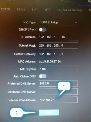
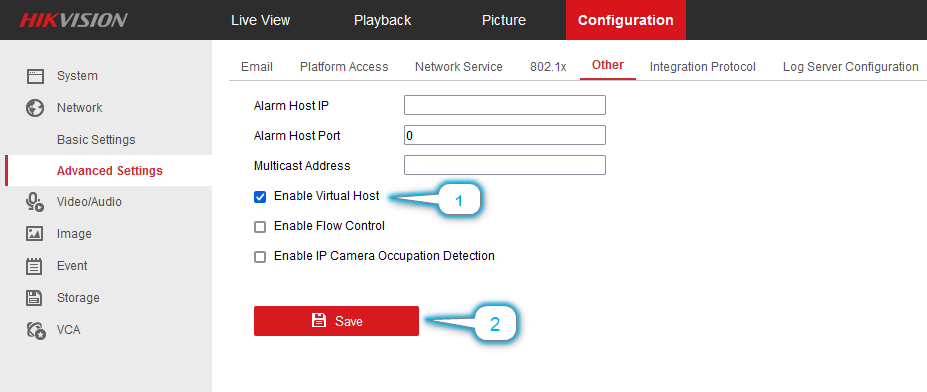
Step 1 - Enable the NVR Virtual Host Feature
This setting may be found elsewhere on earlier versions of the firmware.
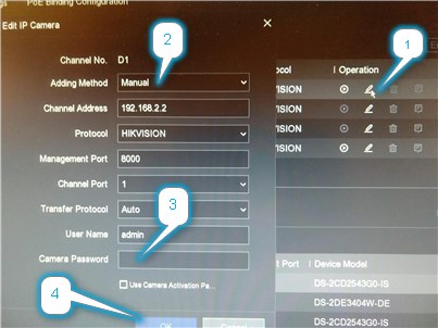
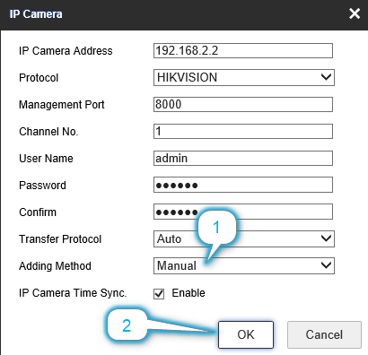
Step 2 - Set Camera IP Configuation to Manual Mode
From the NVR Console
From the NVR Web Interface
Step 3 - Set Default Gateway on Camera

Step 4 - Define Static Route on Router
Other routers may use CIDR notation by combining the destination subnet and subnet mask like this: 192.168.2.0/24.

End of Document